Injection molding services
Mold the product.
Plan the transition.
Engineering-led injection molding for product housings and functional components, with tooling, polymer, finish, and production intent reviewed before quotation.
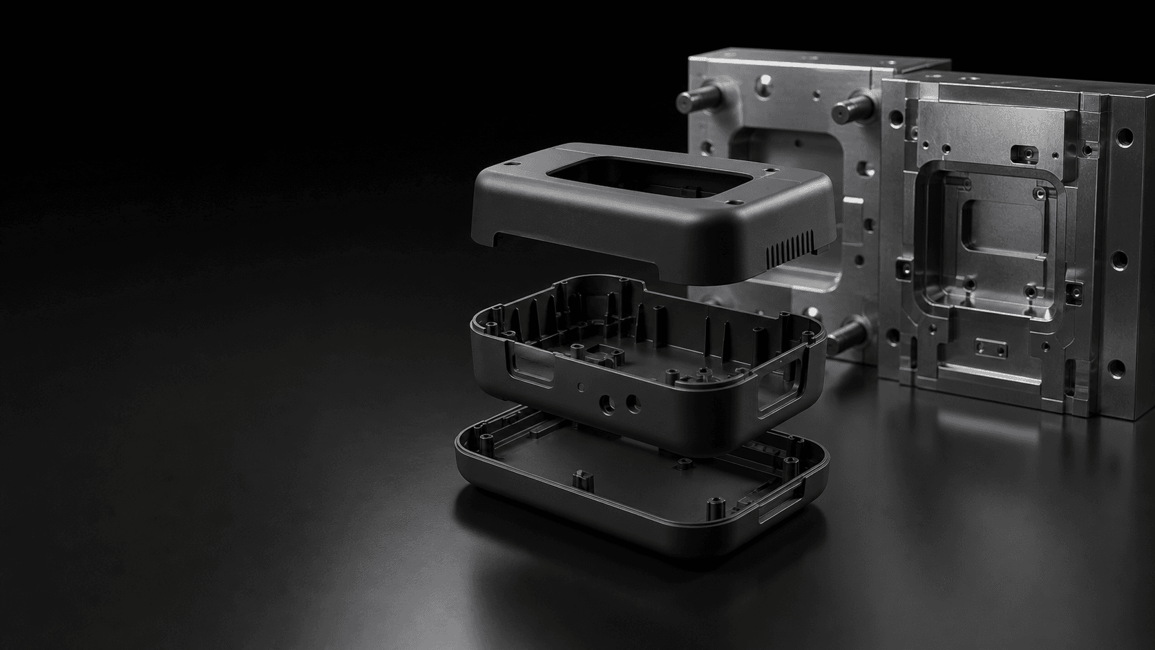
CONCEPT VISUAL / MOLDED ENCLOSURE
Injection overview
A molded part is a production system.
Injection molding connects part design, polymer behavior, tooling decisions, process control, and assembly intent. A useful review considers the complete system—not only the visible geometry.
01
Part intent
Function, load, environment, interfaces, and visible surfaces establish what the molded part must achieve.
02
Tooling intent
Parting, gating, ejection, cooling, access, and expected change influence the tooling strategy.
03
Production intent
Quantity context, release criteria, repeat demand, and assembly needs shape the transition plan.
Tooling strategy
Tooling should reflect where the product is going.
The proposed tooling route is aligned to design maturity, production intent, expected change, surface requirements, and commercial scope. Tool life and construction details are confirmed per project—not assumed.
Requirement alignment
CAD, drawings, material intent, quantities, cosmetic zones, inspection needs, and assembly context are reviewed together.
Tooling concept
Parting, gate, ejection, feature access, and change-sensitive areas are evaluated before a tooling scope is proposed.
Change strategy
Known design risks and likely revisions are surfaced so the release plan can reflect the product's maturity.
Production handoff
Sampling expectations, approval criteria, documentation, and production release conditions are agreed in the project scope.
Molding capabilities
Capability is confirmed against the part, the polymer, and the production brief.
No press tonnage, tool life, dimensional envelope, cycle performance, or production volume is implied without engineering review.
Molded part geometry
Wall transitions, ribs, bosses, undercuts, parting, gating, and ejection are reviewed from CAD.
Tooling route
Tooling scope is proposed around design maturity, production intent, finish, and expected change.
Production scope
Quantity, release criteria, repeat demand, and timing are confirmed before quotation.
Secondary requirements
Inserts, marking, finishing, assembly, packaging, and documentation are reviewed when requested.
Polymer materials
Select the polymer from the product requirements.
Exact resin grades and availability are confirmed during review. Provide performance, regulatory, color, finish, and documentation requirements rather than relying on an assumed material range.
Performance profile
Mechanical loading, temperature, environment, impact, wear, electrical behavior, and assembly conditions guide the review.
Process behavior
Flow, shrinkage, moisture sensitivity, dimensional stability, and surface response must align with the part geometry.
Supply & documentation
Specify the exact grade, color intent, applicable standard, source constraints, and required material records for confirmation.
Design considerations
Design the part and the molding logic together.
These principles support a more useful engineering review. Final decisions depend on the selected polymer, geometry, tooling route, cosmetic intent, and approved drawing.
Wall transitions
Consistent, intentional wall behavior helps reduce abrupt changes in flow, cooling, appearance, and dimensional response.
Draft & release
Surfaces should support part release in relation to texture, depth, geometry, and the proposed opening direction.
Ribs & bosses
Structural features should be reviewed with the surrounding wall, load path, fastening method, and visible surface in mind.
Parting & undercuts
Parting lines, shutoffs, side actions, and undercuts affect tooling complexity, appearance, maintenance, and change strategy.
Gate & ejection intent
Identify sensitive functional and cosmetic zones so gate and ejection concepts can be evaluated against the product brief.
Critical requirements
Use clear datums, functional tolerances, assembly relationships, and cosmetic references to define acceptance intent.
Prototype to production workflow
Move forward through controlled release points.
The workflow connects product learning to production intent without implying a fixed timeline. Each release point is defined by the approved project scope.
Define intent
Share the part, drawing, material requirements, quantities, finish, assembly context, and target timing.
Review design
Align molding risks, cosmetic zones, functional requirements, tooling assumptions, and open decisions.
Release tooling
Approve the defined tooling scope, inputs, change controls, and expected sample criteria before work begins.
Evaluate samples
Review parts against the agreed functional, dimensional, cosmetic, and documentation requirements.
Transition production
Move approved requirements into the agreed production and release workflow for repeat demand.
Surface finish
Appearance starts before the tool is released.
Texture, gloss, color, parting, gate, ejection, and post-process expectations should be treated as engineering inputs. Exact standards and acceptance references are confirmed per project.
Molded surface
Define the intended molded appearance and identify surfaces where process witness or variation is functionally relevant.
Texture intent
Provide a controlled reference and visible zones so texture can be reviewed with draft, geometry, and tooling access.
Cosmetic zones
Separate primary, secondary, and non-visible areas and document color, gloss, match, and defect expectations.
Secondary finish
Requested coating, marking, decoration, or treatment is reviewed for compatibility, adhesion, masking, and scope.
Inspection workflow
Approve the requirements, then evaluate the part.
Inspection and sample approval are defined from the drawing, cosmetic references, functional interfaces, and requested records. No measurement system or report format is implied without agreement.
01
Requirement review
Critical features, datums, cosmetic zones, assembly interfaces, material records, and acceptance criteria are aligned.
02
Sample plan
Sample purpose, evaluation scope, submission expectations, and requested documentation are confirmed.
03
Production checks
Checkpoints are placed according to the approved requirements, feature risk, and production release plan.
04
Release verification
Parts are evaluated against the agreed scope before release, with confirmed records supplied where requested.
Applications
Made for products moving beyond one-off parts.
Injection molding supports product programs that need repeat molded geometry, controlled appearance, and a defined production transition. Suitability is confirmed from the actual requirements.
Product enclosures
External shells developed around assembly, user interaction, internal packaging, interfaces, and cosmetic intent.
Protective housings
Components that locate or protect electronics, sensors, mechanisms, connectors, or other functional elements.
Internal components
Brackets, carriers, guides, covers, and interfaces shaped around load, movement, fastening, and assembly.
Assembly-ready parts
Molded components reviewed with inserts, marking, finishing, joining, packaging, or downstream assembly requirements.
Repeat production
Released parts produced to an agreed drawing, material, finish, inspection scope, and production brief.
FAQ
Before tooling moves forward.
Clear answers about how injection molding projects are reviewed, scoped, and prepared for quotation.
01Do you publish standard tooling lead times?
No fixed lead time is stated for every project. Timing depends on part geometry, design maturity, tooling scope, material, finish, sampling requirements, change cycles, documentation, and production context. It is confirmed after engineering review.
02Which polymer materials are available?
Exact material availability is confirmed from the RFQ. Share the required grade or the product's mechanical, thermal, environmental, cosmetic, regulatory, and documentation requirements for review.
03How is a tooling route selected?
The route is evaluated around design maturity, geometry, expected change, quantity context, surface requirements, material behavior, release criteria, and repeat production intent. Tool life is not assumed without that review.
04What affects an injection molding quotation?
Part design, tooling complexity, material, quantity, finish, inserts, secondary operations, inspection, documentation, packaging, and timing all affect scope. Complete CAD and drawings reduce assumptions.
05Can the design change after tooling release?
A requested change can be evaluated, but its impact depends on the released tooling concept, affected geometry, material, finish, schedule, and current project stage. Changes require scope confirmation before proceeding.
06What should I include with an RFQ?
Include a STEP model, PDF drawing, material and color intent, expected quantities, target timing, finish and cosmetic requirements, critical interfaces, inspection needs, assembly context, and any known future revisions.
Request a molding review
Bring the product intent—not only the shell geometry.
Prepare your CAD, drawing, polymer requirements, quantities, finish, cosmetic references, inspection needs, assembly context, and target timing for engineering review.