Precision sheet metal fabrication
Precision in every fold.
Structure in every line.
Precision sheet metal fabrication for enclosures and structural components, from engineering prototypes to controlled low-volume production.
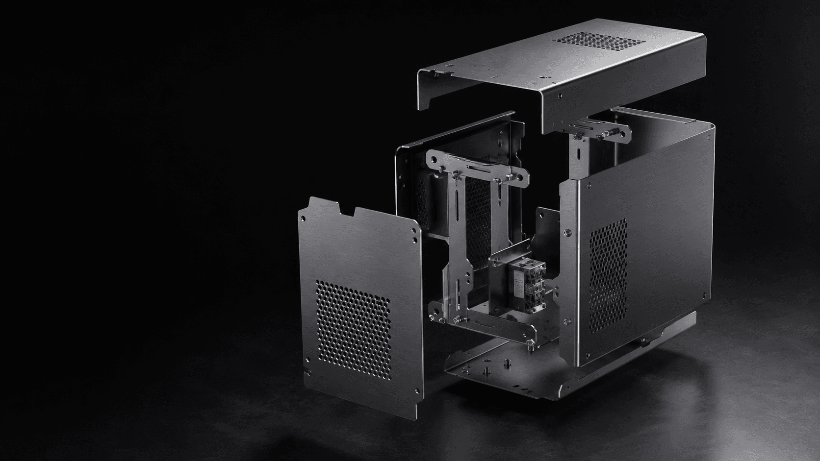
CONCEPT VISUAL / FOLDED ASSEMBLY
Sheet metal overview
Flat geometry becomes a functional structure.
Sheet metal fabrication connects profile geometry, bend behavior, material and thickness intent, hardware, finish, and assembly. The manufacturing plan is reviewed from the finished product backward—not as a collection of isolated cuts and bends.
01
Geometry intent
Panels, openings, interfaces, clearances, flanges, and bend relationships define the structural and assembly logic.
02
Fabrication logic
Flat pattern behavior, bend sequence, access, distortion risk, and secondary operations are considered together.
03
Product intent
Cosmetic zones, internal packaging, hardware, joining, finish, inspection, and service access shape the production scope.
Fabrication capabilities
Capability is defined against the released part.
Fabrication scope is confirmed from CAD, drawings, material and thickness requirements, quantities, finish, and assembly intent. No equipment list or dimensional envelope is implied without review.
Profile & feature planning
External profiles, openings, slots, ventilation patterns, tabs, reliefs, and interface features are reviewed from the flat and formed states.
Bending & forming review
Bend sequence, tool access, return geometry, flange interaction, material behavior, and cosmetic surfaces are evaluated together.
Hardware integration
Fastener, insert, stud, standoff, hinge, latch, and mounting requirements are assessed for access and assembly intent.
Finish & assembly scope
Joining, deburring, surface treatment, marking, assembly, packaging, and documentation are included only after confirmation.
Material and thickness considerations
Material, thickness, and form must work as one system.
No generic material or thickness range is stated. Exact grade, condition, thickness, finish, source constraints, and documentation are confirmed against the geometry and fabrication plan.
Functional requirements
Strength, stiffness, weight, conductivity, thermal behavior, environment, appearance, and joining needs guide material review.
Thickness & geometry
Thickness interacts with bend behavior, minimum features, hole placement, flange proportions, hardware, and structural response.
Supply & documentation
Specify the exact material, condition, thickness, applicable standard, grain or direction needs, and required records.
Design guidelines
Design the flat pattern and the finished assembly together.
These principles support engineering review but do not replace project-specific bend data or an approved drawing. Final guidance depends on material, thickness, geometry, tooling route, finish, and assembly scope.
Bend sequencing
Consider whether each bend remains accessible as the part closes and whether return features create tooling or handling constraints.
Relief & transitions
Bend ends, corners, tabs, slots, and intersecting flanges need deliberate relief and transition geometry.
Tolerance by function
Apply tighter requirements to interfaces, datum relationships, assembly fit, sealing, alignment, and critical clearances.
Datum strategy
Reference stable functional surfaces so fabrication and inspection evaluate the same assembly intent.
Finish allowance
Masking, coating buildup, edge condition, cosmetic zones, grounding, and contact areas should be identified on the drawing.
Assembly access
Plan tool access, fastener installation, component insertion, cable routing, joining, service, and replacement requirements.
Bend radius
The bend follows material behavior.
Inside radius, thickness, material condition, bend direction, tooling route, and cosmetic intent are interdependent. A single universal radius is not applied to every part.
Material relationship
Radius intent is reviewed with the exact grade, condition, thickness, grain or rolling direction, and required formed geometry.
Bend interaction
Adjacent bends, returns, hems, reliefs, corners, and closed profiles influence access and the feasible forming sequence.
Drawing definition
Define finished geometry and critical interfaces; project-specific bend assumptions are confirmed during engineering review.
Hole placement
Place features around the formed condition.
Openings close to bends, edges, hardware, and reliefs can change during forming. Placement should be reviewed in both flat and finished states.
Bend proximity
Holes, slots, vents, and cutouts near a bend are evaluated for distortion, access, function, and visual impact.
Edge & feature spacing
Spacing between openings, sheet edges, reliefs, hardware, and adjacent geometry must support function and fabrication stability.
Finished-state location
Dimension critical openings from functional datums and assembly interfaces rather than relying only on flat-pattern coordinates.
Flanges and hardware
Interfaces need space, access, and sequence.
Flanges and installed hardware affect stiffness, joining, alignment, component clearance, assembly access, finish masking, and serviceability.
Flange geometry
Length, return direction, corner conditions, adjacent bends, and assembly relationships are reviewed with the forming route.
Hardware interfaces
Specify exact hardware, orientation, installation side, retention intent, load, electrical contact, and finish requirements.
Installation sequence
Hardware, joining, finishing, and product assembly must be sequenced so access and protected surfaces remain controlled.
Finish options
Finish belongs in the fabrication brief.
Surface requirements affect material preparation, edge condition, masking, hardware, dimensional intent, appearance, and assembly. Requested finishes are confirmed for compatibility and availability.
As-fabricated intent
Define acceptable surface condition, directional appearance, edge expectations, visible zones, and handling requirements.
Cosmetic surfaces
Identify primary and secondary visible zones and provide controlled color, gloss, texture, and defect references.
Functional treatment
Grounding, contact, sealing, wear, corrosion, adhesion, thermal, and environmental needs should be documented.
Post-process coordination
Requested coating, plating, brushing, marking, or other treatment is reviewed for material compatibility, masking, and scope.
Assembly options
Plan the enclosure as an assembled product.
Assembly scope is reviewed around access, load path, alignment, finish protection, electrical intent, serviceability, and release requirements. Availability is confirmed per project.
Mechanical fastening
Fasteners, hinges, latches, captive elements, and removable interfaces are reviewed with access and service intent.
Inserted hardware
Studs, standoffs, nuts, inserts, and other specified hardware are evaluated for installation, load, finish, and inspection.
Joined subassemblies
Permanent or semi-permanent joining requirements are reviewed for geometry, distortion, access, appearance, and verification.
Integrated assembly scope
Panels, brackets, hardware, finish, marking, packaging, and requested records can be evaluated as one defined release scope.
Typical applications
Built around the product architecture.
Precision sheet metal supports engineering programs that need formed structure, internal packaging, accessible assembly, controlled appearance, and repeat low-volume production.
Precision enclosures
Product housings developed around electronics, controls, displays, connectors, thermal paths, access, and cosmetic zones.
Structural brackets
Load-bearing, locating, mounting, and interface components shaped around stiffness, assembly, and adjacent systems.
Frames & panels
Chassis elements, internal frames, covers, bezels, partitions, and panels defined around complete product geometry.
Electromechanical assemblies
Formed components that package electronics, sensors, power elements, cable routing, airflow, and moving mechanisms.
Prototype to low volume
Released parts and assemblies produced to an agreed material, thickness, drawing, finish, inspection plan, and scope.
Inspection workflow
Verify the formed part in its assembly context.
Inspection scope reflects datums, formed geometry, interfaces, hardware, finish, cosmetic zones, and requested records. No specific equipment or certification is implied without agreement.
01
Requirement review
CAD, drawing, material and thickness, bend intent, critical interfaces, finish, hardware, and records are aligned.
02
Fabrication checkpoints
Checks are placed around feature risk, bend sequence, formed relationships, hardware, and agreed acceptance criteria.
03
Assembly verification
Fit, alignment, clearances, hardware, joining, finish condition, and functional interfaces are reviewed where included.
04
Final release
Parts, assemblies, and requested documentation are evaluated against the approved project scope before release.
FAQ
Before the flat pattern becomes the product.
Straight answers about how precision sheet metal projects are reviewed and prepared for quotation.
01Which sheet metal materials and thicknesses are available?
Exact material, grade, condition, thickness, source requirements, and documentation are confirmed from the RFQ. We do not publish an unverified universal material or thickness range.
02Do you publish standard bend radii?
No single radius applies to every part. Radius depends on material, condition, thickness, grain or rolling direction, tooling route, geometry, finish, and functional requirements. Project assumptions are confirmed during review.
03What files should accompany an RFQ?
Include a STEP model, PDF drawing, material and thickness requirements, finish, quantity, target timing, critical interfaces, hardware specifications, assembly scope, inspection needs, and required documentation.
04Can hardware and assembly be included?
Requested hardware, joining, and assembly can be evaluated as part of the scope. Exact hardware, installation, access, finish, load, inspection, and release requirements must be confirmed before quotation.
05What affects quotation and lead time?
Geometry, material, thickness, bend sequence, quantity, hardware, joining, finish, inspection, documentation, packaging, and target timing all influence scope. Timing is confirmed after engineering review.
06How should cosmetic requirements be defined?
Identify visible zones, viewing intent, surface direction, edge expectations, color, gloss, texture, masking, acceptable variation, and any controlled reference used for approval.
Request a fabrication review
Bring the enclosure geometry. Include the assembly intent.
Prepare your CAD, drawing, material and thickness requirements, quantity, finish, hardware, assembly scope, inspection needs, documentation, and target timing.