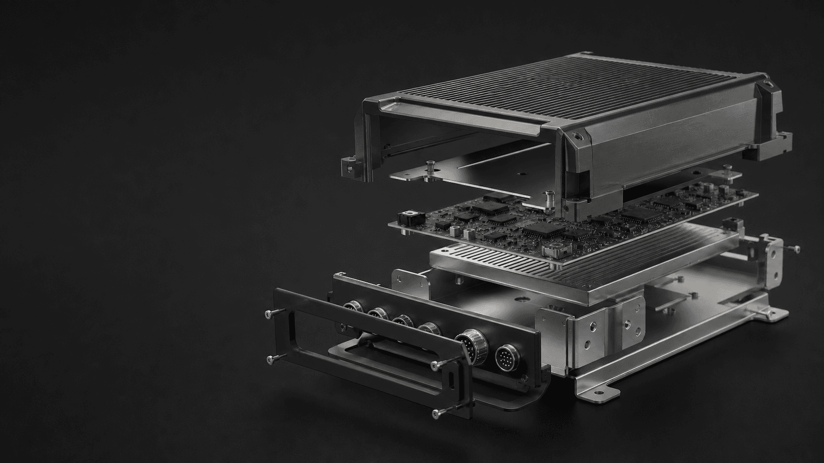
Electronics hardware manufacturing
Protect the electronics.
Control every interface.
Manufacturing support for electronic products where enclosure geometry, heat-management intent, connector alignment, assembly, and industrial design converge.
Conceptual CGI / Representative electromechanical context
Industry context
The enclosure connects every physical requirement.
A successful enclosure is more than a cover. It locates electronics, exposes interfaces, manages handling and heat, supports assembly, and defines much of the finished product experience.
01
Electronics architecture
Board layout, connectors, displays, controls, antennas, sensors, power, and cables establish the mechanical interfaces that must align.
02
Product environment
Installation, handling, temperature, contamination, cosmetic expectations, service access, and mounting context shape the physical design.
03
Build strategy
Prototype quantity, production intent, revision pace, finish fidelity, and assembly volume influence the appropriate manufacturing route.
Engineering challenges
Turn a dense assembly into a controlled product.
Mechanical review connects board-level interfaces to enclosure geometry and the wider manufacturing, finishing, and assembly sequence.
Packaging and access
Boards, cables, controls, batteries, displays, fasteners, and tooling access must fit within an enclosure that can still be assembled and serviced.
Heat-management intent
Contact surfaces, airflow paths, vents, spreaders, and heat sinks require defined interfaces and customer-led system validation.
Connector stack-up
Board position, panel openings, external cables, retention, and datum chains must support mating and protect sensitive electronics.
Finish and electrical context
Cosmetic surfaces, grounding points, masked areas, coatings, antennas, and EMI-related intent need explicit drawing and process requirements.
Typical component types
Mechanical components for electromechanical products.
These categories describe common applications, not guaranteed specifications. Each part is reviewed for process, material, finish, quantity, and inspection fit.
Precision enclosures
Machined, fabricated, or molded housings developed around electronics, controls, I/O, mounting, assembly, and visible product surfaces.
Heat-management components
Customer-designed spreaders, interface plates, heat-sink structures, ducts, and mounting elements that support a defined thermal architecture.
Panels, brackets, and frames
Connector panels, board supports, internal frames, mounting brackets, trays, covers, and cable-management parts.
Control and sensor housings
Bezels, display surrounds, control bodies, sensor enclosures, and interface components where alignment and appearance meet.
Assembly and test hardware
Fixtures, carriers, alignment aids, development chassis, and integration parts used to support repeatable build and evaluation work.
Manufacturing solutions
Use the process that supports the assembly intent.
Process selection reflects geometry, material, quantity, finish, interface control, and product stage. Electrical and thermal performance require separate system validation.
Material considerations
Mechanical behavior, finish, and electrical context are connected.
Material and finish selection should reflect the product requirement, manufacturing process, operating environment, and downstream assembly—not a generic enclosure convention.
Thermal and structural role
Identify load paths, contact surfaces, heat-flow intent, weight constraints, and form requirements before selecting a material family.
Electrical integration
Grounding, isolation, antenna regions, coating, masking, and EMI-related requirements must be defined by the customer and validated at system level.
Surface and environment
Cosmetic zones, abrasion, corrosion context, handling, cleaning, marking, bonding, and fastening can affect finish and process decisions.
Prototype to production
Refine the enclosure with the electronics inside it.
A staged build path helps resolve packaging and interface risk before geometry, finish, assembly, and inspection expectations are released.
01 / LAYOUT
Package
Evaluate board location, connectors, controls, sensors, cables, mounting, clearances, fasteners, and access.
02 / BUILD
Integrate
Assemble functional hardware to test customer-defined fit, thermal, electrical, usability, and service assumptions.
03 / DEFINE
Release
Control CAD, drawings, materials, finishes, masking, hardware, labels, interfaces, and inspection criteria.
04 / CONTROL
Produce
Move the approved configuration into a low-volume workflow with agreed records and assembly scope.
Quality considerations
Inspect the relationships the electronics depend on.
The customer drawing and project review establish critical characteristics, inspection expectations, and documentation. Product-level performance is validated separately.
PCB and connector alignment
Define the board datums, supports, opening positions, retention features, and tolerance relationships that govern mating.
Contact and mounting surfaces
Identify interfaces that support heat-management parts, displays, sensors, seals, controls, or structural attachment.
Finish zones
Separate cosmetic, masked, bonded, grounded, threaded, and hidden surfaces so finishing and inspection expectations remain clear.
Assembly evidence
Define hardware, insert, torque, gap, flush, configuration, and requested inspection records when assembly is included in scope.
Related capabilities
Build the enclosure as a complete product system.
Electronics programs can combine precision interfaces, fabricated structures, molded surfaces, and additive development parts across one controlled assembly.
Electronics FAQ
Start with the assembly. Then review the parts.
A useful RFQ explains the mechanical relationships around the electronics and distinguishes component inspection from system performance validation.
01What should be included in an electronics enclosure RFQ?
Provide CAD, drawings, quantity, material, finish, timing, board and connector context, cosmetic zones, hardware, assembly requirements, critical interfaces, and inspection or documentation expectations.
02Do you validate thermal, EMI, ingress, or electrical performance?
Not by default. Manufacturing and inspection address agreed component requirements. Thermal, EMI, ingress, radio, electrical, safety, and other system-level performance require customer-defined testing and validation unless separately scoped in writing.
03Can one enclosure combine machined, sheet-metal, molded, and printed parts?
Yes. Hybrid assemblies are common where different parts serve different structural, cosmetic, thermal, or development roles. Every component and shared interface still requires project-specific review.
04How should cosmetic surfaces be communicated?
Identify visible zones, finish intent, texture or color references, acceptable process witness areas, masked interfaces, and any agreed appearance criteria on the drawing or project brief.
Start an electronics RFQ
Share the enclosure and the interfaces behind it.
Upload the geometry and describe the electronics context, material, quantity, timing, finish, assembly, cosmetic zones, and inspection expectations for review.